ViewStation Model Numbers
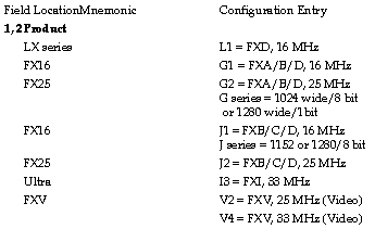
The ViewStation Part Numbers contain information that defines the ViewStation's configuration. You can also get this information from the "hwconfig" command from the Console Window.
Standard configuration for the ViewStation is base, 4 MB DRAM memory, no flashPROM, no communications board, 110 AC power, IBM kybd., mouse, manual, also the video setting, the number of bit planes, monitor type, and monitor cable as appropriate. Component level descriptions of these basic configurations are given below.
The ViewStation is composed of a KIT, which contains a Base (with Circuit Board options), an Options group, and a Monitor. All of these elements are described by values encoded in the model number. The base model number is found on the serial number label located on the back left side of the base.
The KIT consists of four parts:
Circuit Board -- "CB" specified by fields 1 through 9
Base -- "BA" specified by fields 1 through 11 (includes CB)
Options -- "OPT" specified by fields 13 and 14
Monitor -- "MON" specified by field 15
The model number consists of a series of fields with the field location containing values indicating the configuration for that unit. Hyphens are inserted to distinguish kit component groups. The model numbers use these selectors in their appropriate fields.
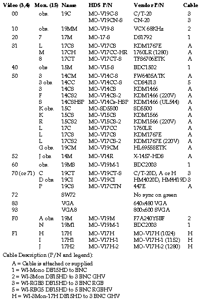
The following table shows ViewStation monitors, with fields 3,4 for the video switch setting and field 15 for the monitor. It also lists monitor part numbers and the video cables needed or supplied.
The 3,4 field sets the circuit board video configuration (field 3 = Hex switch set ting; field 4 = jumpers or other video options). Settings for monitors no longer shipped are included.
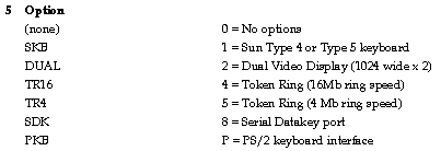
This field sets circuit board options.
This field sets the memory configuration. These values are permitted:
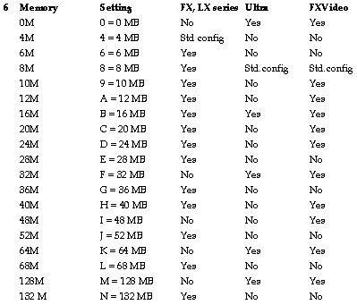
Note: for ViewStation Ultra, the memory must use identical SIMM pairs, so available memory is 8, 16, 32, 64, or 128 MB only.
This field sets the number of video bitplanes.

Field 8 is used as a separator hyphen only "-"
This field specifies the flashPROM board type.

This field specifies the communications options.

This field specifies the AC power setting.

Field 12 is used as a separator hyphen only "-"
FX Option Package Model Numbers
These are entered as a 2 digit value in fields 13 and 14, according to the following table (field 13 specifies the keyboard style, and field 14 is a sequential number for other option groups):
Keyboard values are specifically defined and used as the first digit in the Options table entry:
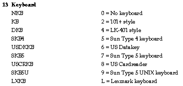
The option packages are defined as follows:
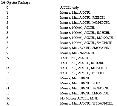
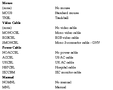
Note that the following mnemonics designate the corresponding parts:
The monitor value is entered in field 15, which appears in the Monitor chart:
Examples:
For Model number = G1F0081-111-28A
Description: FX16 19M 8M 1B FL CM MON
Circuit Board
G1 = FXA, 16 MHz circuit board
F0 = video setting for FX19M, 76 KHz
0 = no circuit board options
8 = 8 MB of memory
1 = 1 bitplane (monochrome)
Base
1 = FlashPROM (both WM, 16 Mb)
1 = Comm board
1 = 120 VAC power
Options
2= 101+ style keyboard
8 = Mouse, Mnl, ACCBL, 3MONCBL
Monitor
A = 19M 76 KHz - F7A240-Y5BF
 Return to the Home Page